Planetary vs Spur vs Worm Gearboxes: A Practical Comparison for Compact Designs
-
 2026.06.08
-
Buying Guides


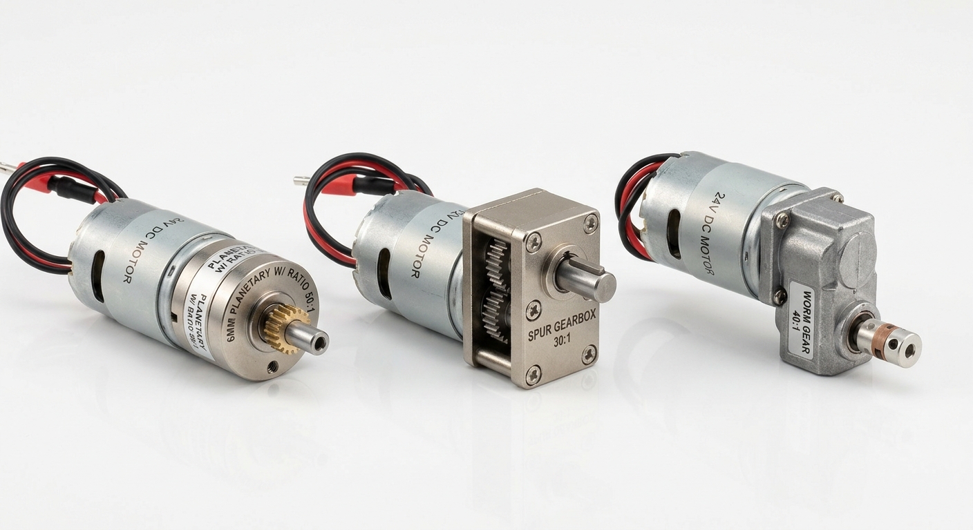
For compact motor designs, the gearbox choice usually comes down to three priorities: torque density, shaft orientation, and cost. Choose a planetary gear motor when you need high torque, low backlash, and an inline package. Choose a spur gear motor when efficiency, simple construction, and BOM cost matter most. Choose a worm gearbox when the design requires a 90° output or resistance to back-driving.
The best option is not necessarily the gearbox with the highest torque rating. It is the one that matches the actual load profile, duty cycle, speed, mounting space, positioning requirements, and expected service life of the finished product.
The 30-Second Gearbox Decision Framework
- Need high torque in a small coaxial footprint? Start with a planetary gearbox.
- Need an economical and efficient drive for a predictable light load? Start with a spur gearbox.
- Need a right-angle output or resistance to back-driving? Evaluate a worm gearbox.
- Need tight positioning and frequent direction changes? A low-backlash planetary gearbox is usually the strongest candidate.
- Need long continuous operation? Compare total gearbox efficiency and thermal performance before making the final choice.
This framework covers most preliminary selections. The final decision should still be checked against continuous torque, peak torque, output speed, starting load, radial and axial forces, and duty cycle. Our torque and speed specification checklist explains the key values to confirm before selecting a gear motor.
How Planetary, Spur, and Worm Gearboxes Transmit Power
The internal power path explains most of the performance differences between these three gearbox types.
Planetary gearbox structure
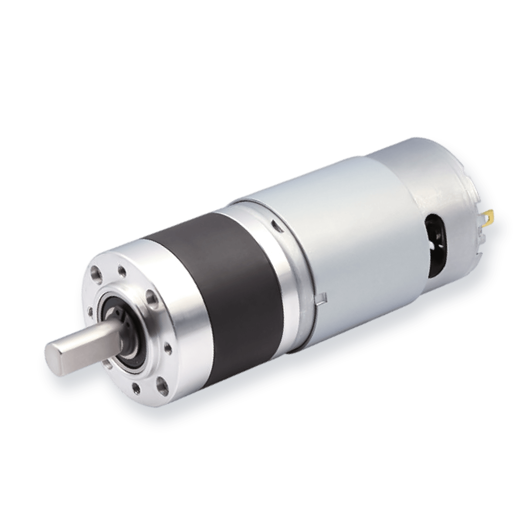
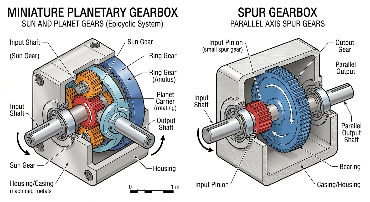
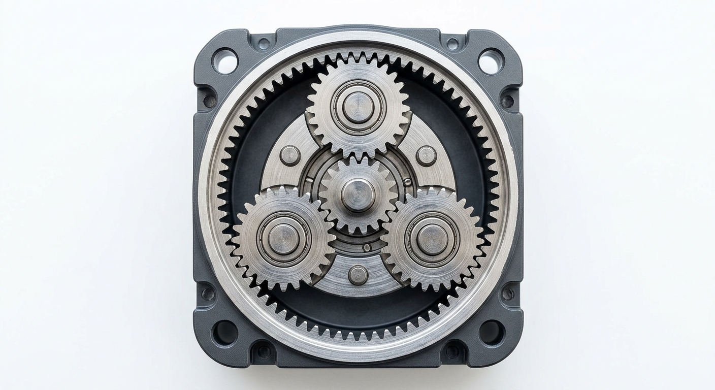
A planetary gearbox uses a central sun gear, multiple planet gears, a planet carrier, and an internal ring gear. Several planet gears share the transmitted load at the same time. This load-sharing arrangement allows a planetary gearbox to deliver high torque within a relatively small, coaxial package.
Spur gearbox structure
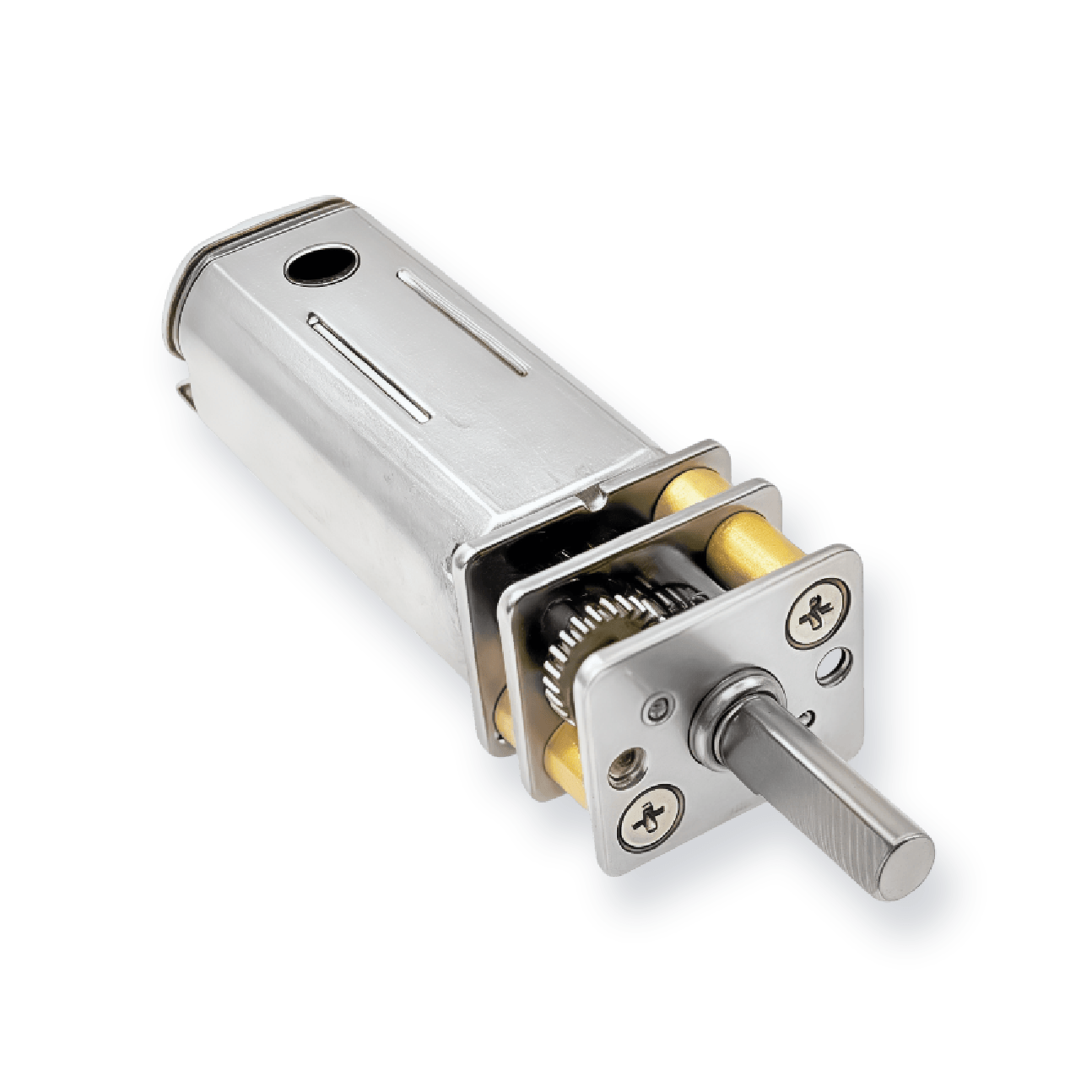
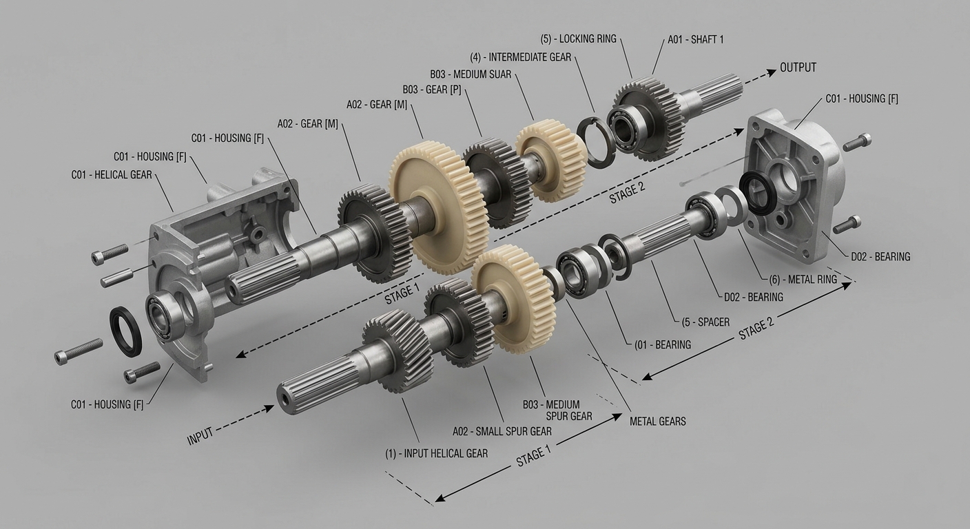
A spur gearbox uses straight-cut gears mounted on parallel shafts. Reduction is created by passing power through one or more gear pairs. The structure is straightforward, efficient, and economical to manufacture, although the required gearbox length and accumulated backlash can increase as more stages are added.
Worm gearbox structure
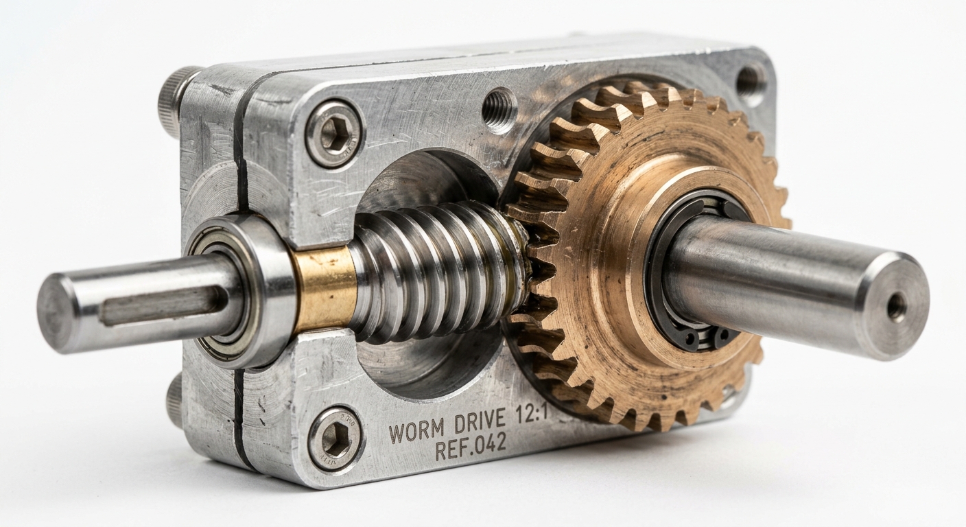
A worm gearbox uses a screw-shaped worm meshing with a worm wheel. The input and output shafts are normally positioned at 90° to each other. The sliding contact between the worm and wheel enables large reductions in a compact stage, but also produces more friction and heat than typical spur or planetary gear meshes.
Planetary vs Spur vs Worm Gearboxes at a Glance
| Selection criterion | Planetary gearbox | Spur gearbox | Worm gearbox |
|---|---|---|---|
| Torque density | High | Low to moderate | Moderate to high |
| Typical efficiency | High | Highest of the three | Lower and ratio-dependent |
| Standard backlash | Low to moderate | Moderate and cumulative | Moderate |
| Shock-load capacity | Good when properly sized | Limited at comparable size | Application-dependent |
| Output orientation | Inline | Parallel or offset | Right-angle |
| Back-driving resistance | Low | Low | Can be high |
| Continuous-duty suitability | Good with correct lubrication and sizing | Good because of high efficiency | Requires careful thermal evaluation |
| Relative cost | Higher | Lowest | Moderate |
| Typical applications | Robotics, medical devices, actuators and power tools | Appliances, dispensers, locks and light automation | Valve drives, window lifts, locks and right-angle mechanisms |
These are general tendencies rather than guaranteed specifications. Gear material, tooth geometry, bearing arrangement, lubrication, manufacturing tolerance, reduction ratio, and housing stiffness can significantly change the performance of an individual gearbox.
Planetary Gearboxes: High Torque in a Coaxial Package
A planetary gearbox is usually the first option to evaluate when torque per unit volume matters. Because multiple planet gears share the load, the gearbox can transmit more torque than a similarly sized single-path spur gear train, provided that the gears, carrier, bearings, and housing are designed for the required load.
Choose a planetary gearbox when you need:
- High continuous or peak torque within a restricted diameter
- An inline motor and output shaft arrangement
- Lower backlash for positioning or repeatable movement
- Better tolerance of repeated acceleration and deceleration
- Higher reduction ratios without an excessively long spur gear train
- A rigid drivetrain for robotic joints, grippers or compact actuators
Typical planetary gearbox applications
Planetary gear motors are widely used in robotic joints, electric grippers, surgical instruments, syringe and infusion pumps, camera gimbals, powered tools, automated laboratory equipment, and compact linear actuators. For pre-matched motor and gearbox combinations in this size range, see our planetary gear motors built on the same 10–36 mm platforms.
For example, a compact dosing mechanism that requires repeatable low-speed movement and relatively high output torque may benefit from a planetary gearbox because it can provide the required reduction without greatly increasing the gearbox diameter. The exact ratio and motor size would still need to be calculated from the screw lead, required linear force, acceleration profile, and permitted backlash.
Planetary gearbox limitations
Planetary gearboxes contain more components and require tighter manufacturing control than conventional spur gearboxes. They therefore normally cost more. Multiple gear meshes can also generate audible gear noise at high input speeds, especially when straight-cut gears are used.
Standard miniature planetary gearboxes are not automatically precision gearboxes. Backlash varies substantially between standard, enhanced, and precision grades. When positioning accuracy matters, request a defined backlash limit rather than relying only on the word “planetary.”
Spur Gearboxes: Efficient, Simple, and Cost-Effective
Spur gearboxes remain one of the most practical options for compact motor products. Their simple parallel-shaft construction keeps manufacturing costs low and can provide excellent mechanical efficiency when the load, ratio, and gear materials are properly matched.
Choose a spur gearbox when you need:
- A cost-sensitive drive for medium- or high-volume production
- High transmission efficiency
- A light and predictable output load
- Simple on-off or single-direction movement
- Moderate positioning accuracy rather than precision motion
- A standard gear ratio that can be produced without complex tooling
Why spur gear motors are used so widely
A well-designed spur gear stage can be highly efficient because the tooth contact is predominantly rolling rather than sliding. This makes spur gear motors suitable for battery-powered devices and applications where reducing power loss is more important than maximizing torque density. Our spur gear motors cover this range in inline and parallel-shaft configurations.
They power many of the products discussed in our guide to mini gear motors in everyday devices, including electric toothbrushes, soap dispensers, vending mechanisms, automated blinds, pet feeders, small kitchen appliances, and lightweight smart-home mechanisms.
Spur gearbox limitations
A conventional spur gear train does not distribute the load across several planet gears. This limits torque capacity at a comparable gearbox diameter and can make the teeth more vulnerable to repeated shock loads or hard stops.
Backlash also accumulates as additional stages are added. A single stage may have acceptable clearance, while a long multi-stage train can produce noticeable movement at the output. The effect depends on tooth quality, center distance, shaft support, housing stiffness, and the number of stages.
At light loads and moderate speeds, a well-made spur gearbox can be quiet. At higher speeds or under heavier load, straight-cut teeth may produce a distinct gear whine. Noise should therefore be measured at the actual operating torque and speed rather than under no-load conditions.
Worm Gearboxes: Right-Angle Transmission and Back-Driving Resistance
A worm gearbox is often selected because of its packaging geometry rather than torque density alone. It changes the direction of power transmission by 90° in a single stage, allowing the motor to sit beside the driven mechanism instead of directly behind it.
Choose a worm gearbox when you need:
- A right-angle output in a flat or space-constrained enclosure
- A relatively large reduction ratio in one gear stage
- Quiet low-speed operation
- Resistance to the output load driving the motor backward
- A compact drive for locks, valves, windows, cameras or adjustment mechanisms
When back-driving resistance matters
Worm drives are commonly used where the output should resist movement after power is removed, such as electric door locks, window lifts, valve actuators, camera tilt mechanisms, and small lifting or adjustment systems. Our worm gear motors are built for these right-angle layouts.
However, a worm gearbox should not automatically be described as self-locking based only on its reduction ratio. True self-locking depends on lead angle, friction coefficient, lubrication, material combination, vibration, wear, temperature, and the direction of the applied load. For safety-critical holding, use a brake, mechanical lock, or other dedicated holding device unless the self-locking behavior has been validated under all operating conditions.
The efficiency and heat trade-off
The worm slides across the worm wheel instead of relying mainly on rolling contact. This creates more friction, reduces efficiency, and converts more input power into heat. Efficiency can vary widely depending on ratio, lead angle, speed, lubrication, and gear materials.
Worm gear motors can work well in intermittent-duty applications, but continuous-duty designs require a thermal check. Oversizing the motor without evaluating the gearbox can still result in excessive housing temperature, lubricant degradation, and shortened service life. See our guide to micro gear motor overheating and practical fixes for common causes and corrective actions.
Match the Gearbox to the Load Profile
Nominal torque is only one part of gearbox selection. The shape of the load over time often determines whether a gearbox performs reliably or fails prematurely.
- Continuous, steady load: Spur and planetary gearboxes are usually the first options because of their higher efficiency. A worm gearbox requires additional thermal evaluation.
- Intermittent high torque: Planetary gearboxes offer strong torque density, while worm gearboxes may be useful when right-angle packaging or holding resistance is required.
- Frequent reversing: A low-backlash planetary gearbox is generally easier to control. Spur gearboxes may also work when accumulated backlash remains acceptable.
- Repeated shock loads: Planetary gearboxes with suitable metal gears, carrier construction, bearings, and lubrication are usually better suited than lightweight spur gear trains.
- Long idle periods with short operating bursts: A spur gearbox may provide the required performance at a lower cost.
- Load holding after power-off: Evaluate a worm gearbox, brake motor, electromagnetic brake, or mechanical locking solution.
A common selection mistake is using a worm gearbox for a continuously operating mechanism solely because the application needs resistance to back-driving. The gearbox may hold the load effectively but waste too much power during operation. In this situation, a more efficient gearbox combined with a brake may provide better thermal performance and service life.
A Five-Step Selection Process
1. Calculate continuous and peak output torque
Determine the torque required during normal operation, startup, acceleration, hard stops, jams, and abnormal loading. Do not size the gearbox from the average load alone. Peak torque must remain within the permitted intermittent or emergency limit for the required duration.
2. Define the required output speed and ratio
Calculate the nominal gearbox ratio from motor speed and required output speed, then check the actual available ratio. Also account for speed loss under load, motor tolerance, gearbox efficiency, and the effect of the power supply.
3. Confirm the duty cycle
Record operating time, rest time, starts per hour, reversing frequency, and ambient temperature. A gearbox that works for a five-second cycle may overheat when operated continuously.
4. Set the positioning and backlash requirement
Specify how much output movement is acceptable when direction changes. Precision positioning may require a low-backlash planetary gearbox, an output-side encoder, mechanical preload, or a combination of these measures.
5. Check the available installation envelope
Confirm maximum diameter, total length, shaft orientation, mounting interface, cable exit, output shaft dimensions, and any nearby components. Packaging constraints can eliminate an otherwise suitable gearbox before detailed performance comparisons begin.
Size, Weight, and Mounting Constraints
Inline versus right-angle output
Planetary gearboxes normally keep the motor shaft and output shaft on the same centerline. Many spur gearboxes use parallel or offset shafts, although inline spur arrangements are also available. Worm gearboxes normally place the output shaft at 90° to the motor.
Inline configurations work well in cylindrical products, pen-style instruments, tubular actuators, and mechanisms with available axial length. A right-angle worm gearbox is often more suitable for smart locks, compact camera mounts, valve drives, and other flat enclosures where the motor needs to sit beside the output.
Diameter versus total length
A planetary gearbox can provide high torque without greatly increasing its diameter, but additional stages still increase total length. A multi-stage spur gearbox can also become long when a large reduction ratio is required. Compare complete motor-and-gearbox dimensions rather than judging the installation only by gearbox type.
Radial and axial output loads
Permitted radial and axial loads depend primarily on the output bearing arrangement, shaft diameter, bearing spacing, housing rigidity, and load position. Do not assume that one gearbox topology will automatically support a pulley, belt, pinion, or lead screw. Request the allowable radial and axial load values at the actual shaft overhang.
Noise, Backlash, and Positioning Accuracy
Noise and backlash are often treated as fixed characteristics of a gearbox type, but actual results depend on tooth profile, material, lubrication, speed, load, assembly quality, and housing resonance. Component-level precision gears and controlled manufacturing tolerances can be just as important as the basic gearbox topology.
Noise considerations
- Worm gearboxes can provide smooth and quiet low-speed movement, although friction and surface finish strongly affect the result.
- Planetary gearboxes have several simultaneous mesh points and may produce gear whine at high input speeds. Helical gearing can reduce noise but adds complexity and axial force.
- Spur gearboxes can operate quietly under light load, but multi-stage straight-cut gear trains may become more audible as speed, load, or wear increases.
For products used near patients, operators, or microphones, test sound pressure and sound quality inside the real enclosure. A gearbox that sounds acceptable on a bench may excite a plastic housing and become noticeably louder in the final product.
Backlash considerations
Low-backlash planetary gearboxes generally provide the strongest starting point for bidirectional positioning. Standard planetary units may still have measurable angular clearance, while precision versions use tighter tolerances or preload to reduce it.
In a spur gearbox, clearance from each gear stage contributes to total output backlash. A long multi-stage gear train can therefore produce more lost motion than a shorter gearbox with a similar overall ratio.
An encoder mounted on the motor shaft measures motor position, not necessarily the exact position of the gearbox output. It cannot directly observe movement lost inside the gear train. An output-side encoder can allow the controller to correct final output position, although mechanical backlash may still affect reversal response, stiffness, and settling time.
What Engineers Commonly Choose for Different Applications
Robotic joints and electric grippers
Planetary gearboxes are commonly selected because robotic mechanisms need high torque density, compact inline packaging, frequent reversing, and controlled backlash. Encoder feedback is often added for closed-loop positioning.
Compact power tools
Planetary gearboxes are frequently used in cordless screwdrivers, miniature drills, and other compact tools because they can transmit high torque and tolerate repeated acceleration and load changes within a small diameter.
Smart-home products and appliances
Spur gear motors are often sufficient for soap dispensers, pet feeders, vending mechanisms, automated blinds, and lightweight appliance adjustments. These applications generally prioritize cost, efficiency, and predictable intermittent movement.
Electric locks and window mechanisms
Spur and worm gearboxes are both common. Spur gearboxes offer higher efficiency, while worm gearboxes provide right-angle packaging and greater resistance to back-driving. The correct option depends on available space, holding requirements, cycle life, and temperature limits.
Medical pumps and diagnostic equipment
Planetary gearboxes are often paired with coreless DC motors, BLDC motors, or stepper motors when the system requires smooth low-speed movement, repeatable positioning, and high torque within a small package. Spur gearboxes may still be appropriate for lower-load auxiliary mechanisms.
Linear actuators
Light-duty actuators may use a spur gearbox and lead screw to control cost. Higher-force or more compact actuators often use planetary gearboxes. Worm drives may be considered when the motor must sit perpendicular to the screw or when back-driving resistance is important.
Valve and damper actuators
Worm gearboxes are useful when right-angle output and holding resistance are important. Planetary gearboxes may be preferred when efficiency, frequent cycling, or precise bidirectional control has greater priority.
Pairing the Gearbox with the Right Motor
The gearbox and motor must be selected as one drive system. Motor speed, starting torque, current draw, control method, thermal limits, and expected brush or bearing life all affect the final gearbox choice.
- Brushed DC motor with spur gearbox: A practical low-cost combination for consumer products and intermittent light-duty mechanisms.
- Brushed DC motor with planetary gearbox: Suitable when higher torque density is required but the application does not justify the cost of a BLDC drive.
- BLDC motor with planetary gearbox: A strong option for long-life, high-duty-cycle, and precision applications in robotics, medical equipment, and automation.
- Coreless DC motor with planetary gearbox: Useful where low rotor inertia, rapid response, and smooth low-speed control are required.
- Stepper motor with planetary gearbox: Suitable for compact open-loop or closed-loop positioning that requires higher output torque and reduced speed.
- Brushed or BLDC motor with worm gearbox: Suitable for right-angle drives and mechanisms that benefit from resistance to back-driving.
Our brushed vs brushless DC motor selection guide compares motor lifetime, efficiency, control requirements, noise, and total cost. For a broader overview, see the complete guide to DC motor types.
Cost, Lead Time, and Customization
Gearbox cost depends on more than topology. Diameter, gear material, heat treatment, bearing grade, lubrication, backlash tolerance, inspection requirements, order volume, and customization can all change the final quotation.
- Spur gearboxes generally offer the lowest component and assembly cost. Standard ratios and molded gears can support short lead times for volume projects.
- Worm gearboxes usually sit between spur and planetary options. Material selection for the worm wheel, surface treatment, lubrication, and shaft design influence both cost and delivery time.
- Planetary gearboxes normally cost more because they contain additional gears, pins, bearings, and carrier components. Low-backlash grades require tighter control and more inspection.
For prototypes, begin with a standard motor and gearbox combination that can validate the mechanical concept. Once torque, speed, temperature, noise, and lifetime have been tested, the design can be optimized with a custom ratio, output shaft, mounting flange, cable, connector, encoder, or lubrication system.
Our guide to when to choose a custom gearbox instead of a standard gear motor explains which requirements typically justify customization.
Gearbox Life and Maintenance Considerations
There is no universal service-life figure for planetary, spur, or worm gearboxes. Actual life depends on load factor, operating speed, start-stop frequency, shock loading, lubrication, contamination, alignment, ambient temperature, and manufacturing quality.
The most common causes of premature gearbox failure include:
- Operating continuously above the rated torque
- Repeated stall or jam conditions
- Excessive gearbox temperature
- Insufficient or unsuitable lubrication
- Contamination entering the gear train
- Unsupported radial or axial output loads
- Frequent reversing with excessive backlash or impact
- Misalignment between the gearbox and driven mechanism
Correct sizing usually has a greater effect on life than simply choosing a more expensive gearbox. Allowing an appropriate torque margin and controlling temperature can significantly reduce tooth wear, bearing damage, lubricant breakdown, and motor overload. See our guide on extending DC gear motor service life for practical design and maintenance recommendations.
Final Gearbox Selection Checklist
Before approving a compact gear motor, confirm the following information with the supplier:
- Rated continuous output torque
- Permitted peak or intermittent torque
- Output speed at the actual operating load
- Gear ratio and ratio tolerance
- Gearbox efficiency at the intended speed and load
- Maximum input speed
- Backlash limit and measurement method
- Permitted radial and axial shaft loads
- Duty cycle and allowable operating temperature
- Noise test conditions
- Expected life under the specified load profile
- Lubrication and maintenance requirements
- Whether worm gearbox self-locking has been validated
- Motor voltage, current, control method, and encoder requirements
Choosing the Right Gearbox for Your Compact Motor Design
Choose planetary when torque density, rigidity, compact inline packaging, and controlled backlash justify the higher cost. Choose spur when the load is predictable and efficiency, simplicity, and unit cost are the main priorities. Choose worm when a right-angle layout or resistance to back-driving provides a clear mechanical advantage and the design can accommodate its lower efficiency.
The final selection should be based on the complete operating profile rather than one headline specification. Torque, speed, duty cycle, backlash, shaft loading, temperature, noise, mounting space, control method, and production volume all need to be considered together.
Send SLW Motor your required torque, output speed, voltage, duty cycle, installation envelope, shaft orientation, and positioning requirements. We can recommend suitable options from our compact motor and gearbox range or evaluate a customized configuration with the required ratio, output shaft, encoder, wiring, and mounting interface. Contact our engineering team through the SLW Motor contact page.