Why Your Micro Gear Motor Overheats — And 6 Practical Fixes
-
 2026.05.29
-
Design Guides


Your micro gear motor overheats because it’s being asked to deliver more than it was designed for — usually a combination of mechanical overload, wrong voltage, insufficient duty cycle margin, or poor heat dissipation in the housing. The fix is rarely “buy a bigger motor.” In most cases, adjusting the gear ratio, matching the supply voltage properly, improving airflow, or tuning the PWM signal solves the problem in an afternoon.
Below are the six causes we see most often in OEM projects, with practical fixes you can apply today.
First, Know What Counts as “Overheating”
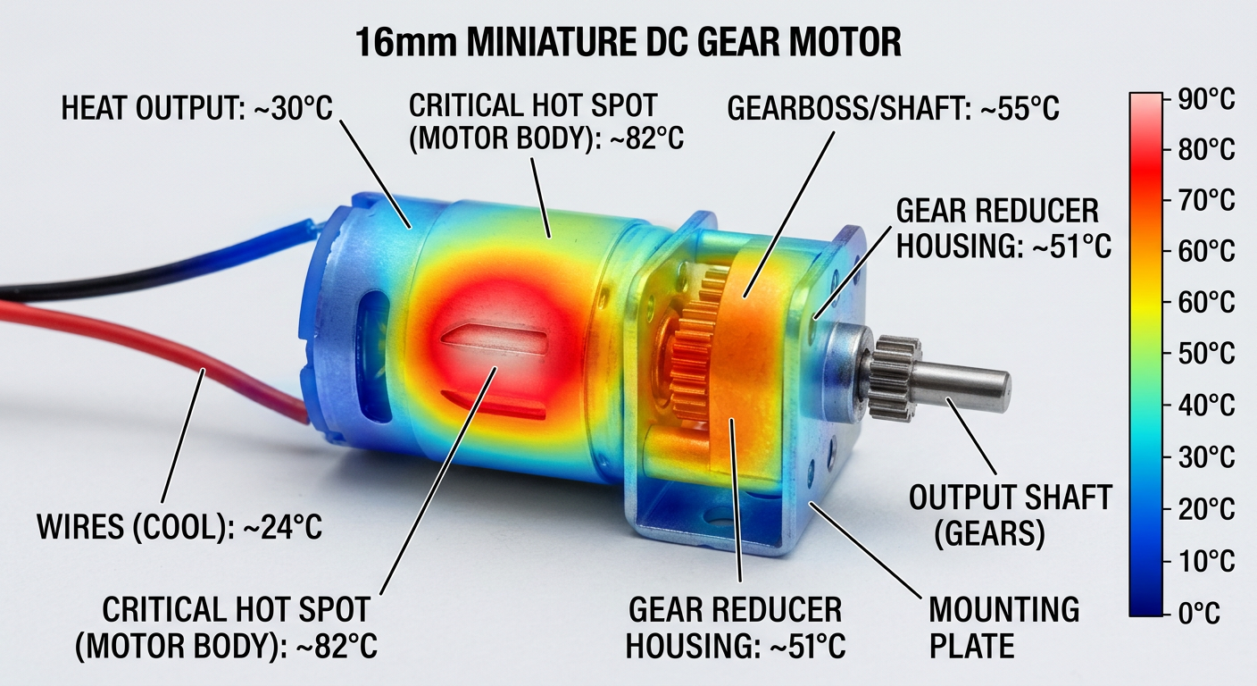
Not every warm motor is in trouble. A brushed DC gear motor running at 60–70°C casing temperature is usually fine — the windings inside can safely reach 100–120°C depending on insulation class (typically Class B at 130°C or Class F at 155°C).
Overheating becomes a real problem when:
- Casing temperature exceeds 80°C in continuous operation
- The motor smells like burnt varnish (a sign the enamel is degrading)
- Performance drops mid-cycle — torque falls, speed sags, current climbs
- Plastic gear stages soften or deform (POM softens around 90°C)
If you don’t have a thermocouple or IR thermometer on hand, put your finger on the case after 10 minutes of running. If you can’t hold it there for 3 seconds, you’re above 60°C and it’s worth investigating.
Cause 1: Mechanical Overload — The Most Common Culprit
Eight times out of ten, an overheating micro gear motor is being asked to push harder than its rated torque. The current draw climbs, copper losses (I²R) increase with the square of current, and heat skyrockets.
How to spot it
Measure the running current and compare it to the datasheet. If your motor is rated for 0.4 A at rated load and you’re seeing 0.9 A in your application, you’re already at roughly 5× the heat dissipation of the rated point.
The fix
Don’t just upsize the motor — that’s expensive and often unnecessary. Instead, increase the gear ratio. A planetary gearbox change from 1:19 to 1:51 reduces the load on the motor shaft by nearly 2.7×, dropping the current draw dramatically while only slowing the output.
For example, a robotics startup using a 12V 25mm gear motor to drive a small conveyor was seeing 75°C casing after 5 minutes. Swapping from a 1:30 to a 1:100 gearbox brought it down to 42°C — same load, no motor change. If you’re not sure how torque and speed interact, review what torque and speed specs you must check before buying a motor.
Cause 2: Wrong Supply Voltage
Running a 12V motor on a 15V supply “to get a bit more speed” is one of the fastest ways to cook the windings. No-load current rises, magnetic losses increase, and the motor spends every second above its thermal budget.
The reverse is also bad. Running a 24V motor at 12V doubles the current needed to deliver the same torque — and copper losses quadruple.
The fix
- Stay within ±10% of rated voltage for continuous operation
- If you need more speed, choose a higher-voltage variant — many compact DC motors are available in 6V, 12V, and 24V windings
- For battery-powered devices, design for the nominal voltage, not the fully charged peak
A medical device team once asked us why their 6V coreless motor kept failing in a handheld surgical tool. The Li-ion pack peaked at 8.4V right after charging. Switching to the 7.4V-rated winding solved the problem instantly.
Cause 3: Duty Cycle Mismatch
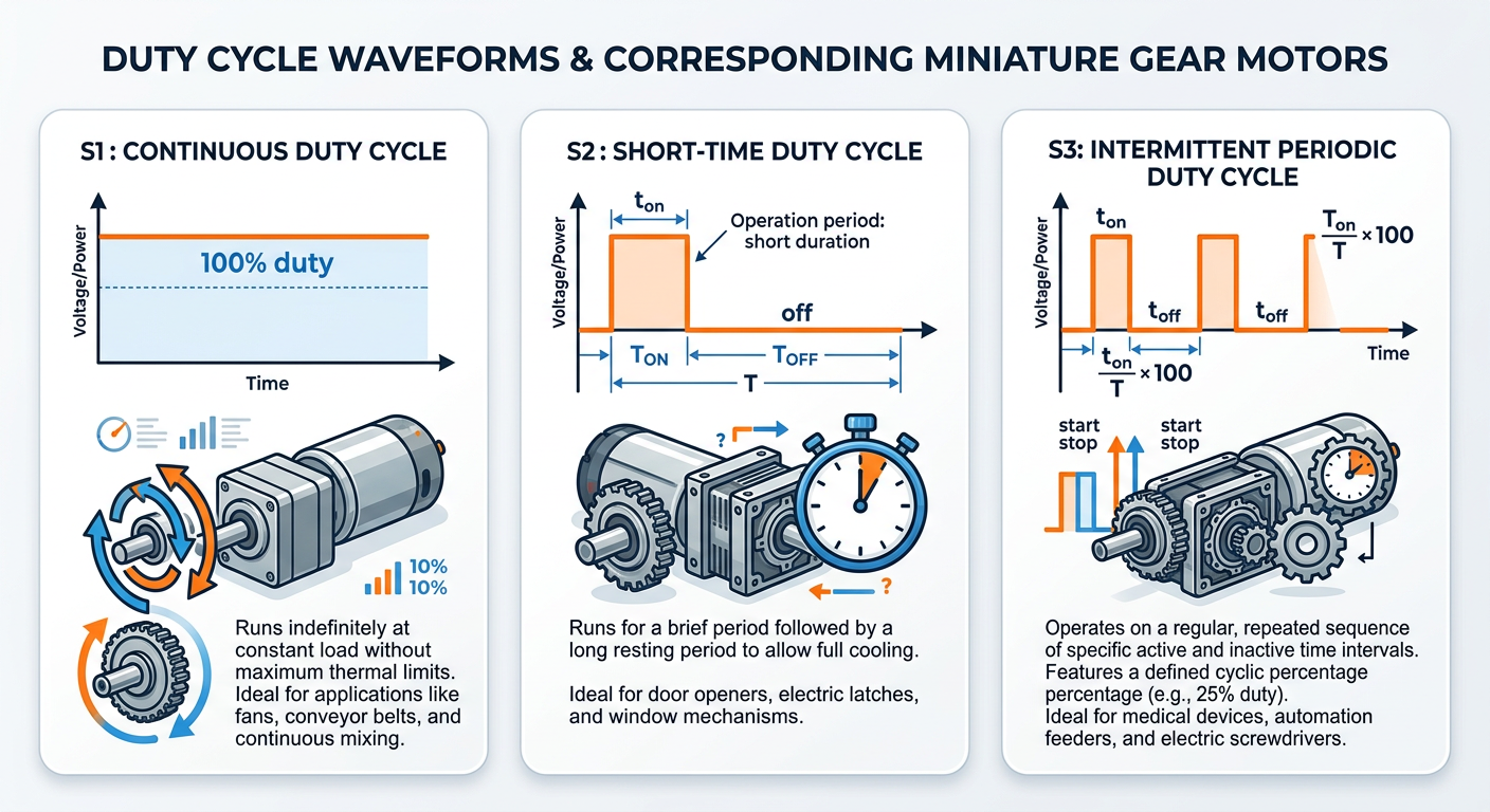
Here’s a mistake I see constantly: engineers spec a motor rated for “S2 — 30 minute duty” and then run it continuously in a 24/7 automation cell. The motor isn’t broken. It’s doing exactly what its thermal mass allows.
Continuous duty (S1) motors are built differently — better lamination, often a metal housing for heat sinking, sometimes a fan or ventilation slots. S2 and S3 rated motors assume cool-down periods.
The fix
Map your real duty cycle. If your application runs 45 seconds on, 15 seconds off, that’s S3 60% — and most micro gear motors handle this fine. If you’re running 95% of the time, you need an S1-rated motor or active cooling.
For applications that switch between bursts and long pauses, you can often get away with a smaller motor than continuous-rated catalogs would suggest. That’s exactly where compact gear motors shine.
Cause 4: Poor Heat Dissipation in the Enclosure
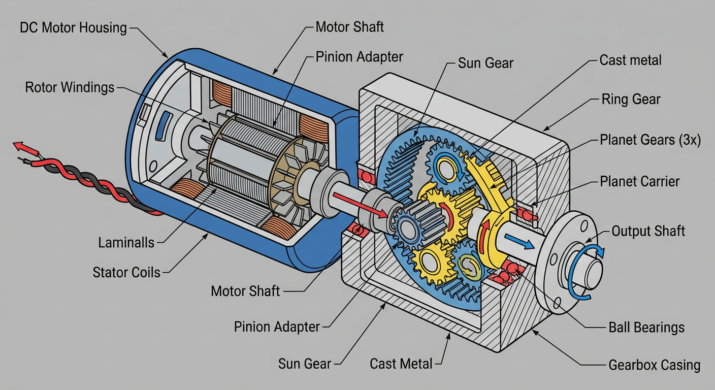
A motor that runs cool on the bench can overheat the moment it’s installed in a sealed plastic housing. Air is a terrible conductor. Without a path for heat to escape, the casing temperature climbs 15–25°C above ambient open-air values.
What actually helps
- Thermal interface — bolt the motor flange to a metal chassis with a thin thermal pad. The chassis becomes your heatsink.
- Vent slots — even small openings near the motor end-bell drop temperatures noticeably. Convection works when given a chance.
- Orient the motor correctly — vertical orientation with the end-bell up encourages natural airflow over the case.
- Avoid foam packing directly against the motor body. Foam traps heat ruthlessly.
For instance, a vending machine designer was getting 85°C on a 30mm worm gear motor inside a sealed dispenser housing. Adding a 1mm aluminum bracket between the motor flange and the metal frame dropped steady-state temperature to 58°C — no electrical change required.
Cause 5: Gearbox Wear or Lubrication Failure
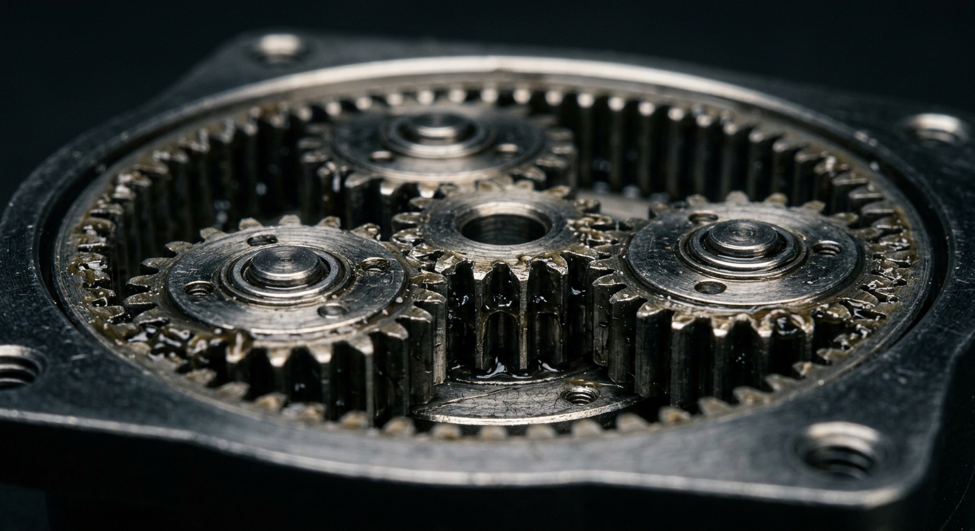
Sometimes the motor is fine, but the gearbox is the heat source. Plastic gears with degraded grease, metal gears running dry, or a damaged bearing all create friction — and friction creates heat that conducts straight back into the motor body.
How to diagnose it
Touch the gearbox housing vs. the motor body separately. If the gearbox is hotter, that’s your problem. Listen for grinding, clicking, or whine that wasn’t there originally.
The fix
- Re-grease with the correct lubricant (lithium-based for most metal gears, PTFE-based for plastic gears — never mix types)
- If gear teeth are visibly worn, replace the gearbox stage
- For applications with frequent direction reversals, consider a planetary gearbox over a spur gear train — planetary stages distribute load across multiple teeth and wear more slowly
For longer-term prevention, our guide on how to extend the lifespan of your DC gear motor covers grease intervals and load management in detail.
Cause 6: PWM Frequency Set Too Low
This one trips up a lot of teams using off-the-shelf motor drivers. A PWM frequency below 5 kHz causes audible whine, current ripple, and extra heating in the windings because the inductive kick on each switching cycle isn’t fully absorbed.
The sweet spot
For most micro brushed DC motors and small BLDC motors, set PWM between 18 kHz and 25 kHz. Above human hearing, low enough that switching losses in the MOSFET don’t dominate.
If you’re using a stepper gear motor, the issue is different — chopper frequency in the driver matters more than the step rate. Modern drivers like the TMC series default to good values, but cheap A4988-based boards often need tuning.
While you’re at it
Check that flyback diodes are in place across the motor terminals (or that your H-bridge has integrated body diodes rated for the application). Missing freewheeling paths cause back-EMF spikes that heat the windings and stress the driver simultaneously.
When the Fixes Aren’t Enough: Time to Reselect
If you’ve worked through all six causes and the motor still runs hot, you’ve outgrown the part. That’s not failure — it’s data. The application needs more thermal headroom than the current motor provides.
A few signs you need to step up:
- You’re at the maximum recommended gear ratio and still overloaded
- Duty cycle is genuinely continuous and the motor is S2-rated
- Ambient temperatures regularly exceed 40°C
- The mechanical envelope can accommodate a slightly larger frame size
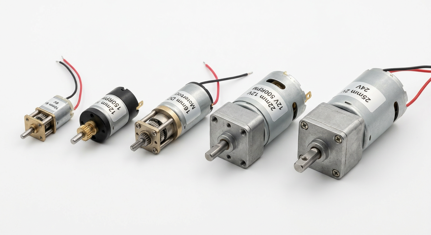
This is also where a custom gearbox configuration often makes more sense than jumping to the next standard size. A purpose-built ratio with the right material gear stack can solve thermal problems within the original mechanical envelope.
If you’re early in the design phase, the complete guide to DC motor types covers brushed, brushless, and coreless trade-offs that affect thermal behavior right from the spec sheet.
Practical Checklist Before You Call It a Motor Problem
Before assuming the motor is defective, run through this in order:
- Measure running current and compare to the datasheet rated current
- Verify supply voltage at the motor terminals under load (not at the power supply)
- Calculate actual duty cycle from your application timing
- Check ambient air temperature near the motor
- Confirm PWM frequency is above 18 kHz
- Listen and feel the gearbox separately from the motor body
- Verify mechanical load — is something binding, dragging, or misaligned?
Nine times out of ten, the answer is in steps 1–4. Mechanical binding from a misaligned shaft coupling is shockingly common — it can double the load on a motor without any visible sign.
If you’re still stuck after working through this list, we’re happy to help diagnose remotely. Send us your duty cycle, load profile, and current draw measurements and our engineering team can usually pinpoint the issue within a day. Reach out here or browse our compact motor and gear motor catalog to see what fits your envelope. For more deep dives into compact motion problems, the SLW Motor blog covers selection, control, and integration topics regularly.