How to Calculate Torque and Gear Ratio for a Small Linear Actuator
-
 2026.06.01
-
Design Guides


To size a small linear actuator, calculate the motor torque using T = (F × L) / (2π × η × i), where F is the axial load in newtons, L is the screw lead in meters, η is the lead-screw efficiency, and i is the gear ratio. The gear ratio itself comes from matching the motor's rated speed to your required linear velocity: i = (motor RPM × L) / (60 × v). Get those two numbers right and the rest of the design — motor type, gearbox, encoder, duty cycle — falls into place quickly.
The Core Formula, Stripped Down
Every small linear actuator is just a rotary motor pushing a screw. The torque the motor has to deliver to lift a load is:
Tmotor = (F × L) / (2π × η × i)
- F — axial force in newtons (load weight × g, plus friction, plus any preload)
- L — screw lead in meters (distance traveled per one screw revolution)
- η — combined efficiency of the screw and gearbox (typically 0.20 – 0.50 for ACME/lead screws paired with planetary gear motors)
- i — gear reduction ratio between motor shaft and screw
That single equation does most of the work. The trap is plugging in optimistic numbers — particularly efficiency — and ending up with a motor that stalls the first time it hits a real load.
Step 1 — Nail Down the Real Load Force
Most sizing errors start here. Engineers calculate the static load and forget everything else.
Your actual axial force is:
F = m × g + Ffriction + Fpreload + m × a
That last term — mass times acceleration — matters when the actuator has to move quickly. A 2 kg payload that accelerates from 0 to 50 mm/s in 0.1 s adds about 1 N of dynamic load on top of the 19.6 N static weight. Small, but it shows up in current draw.
Then add side-load friction. If the actuator pushes a sliding mechanism with its own seals or guides, expect 10 – 30% extra resistance. For vertical lifting, gravity does the work going down — but the screw still has to hold the load, which is a separate self-locking question we'll get to.
For a worked number, assume a medical infusion pump pushing a syringe plunger with 25 N of breakaway force, plus 3 N of seal drag. Design F = 28 N. Round up to 35 N to give yourself headroom.
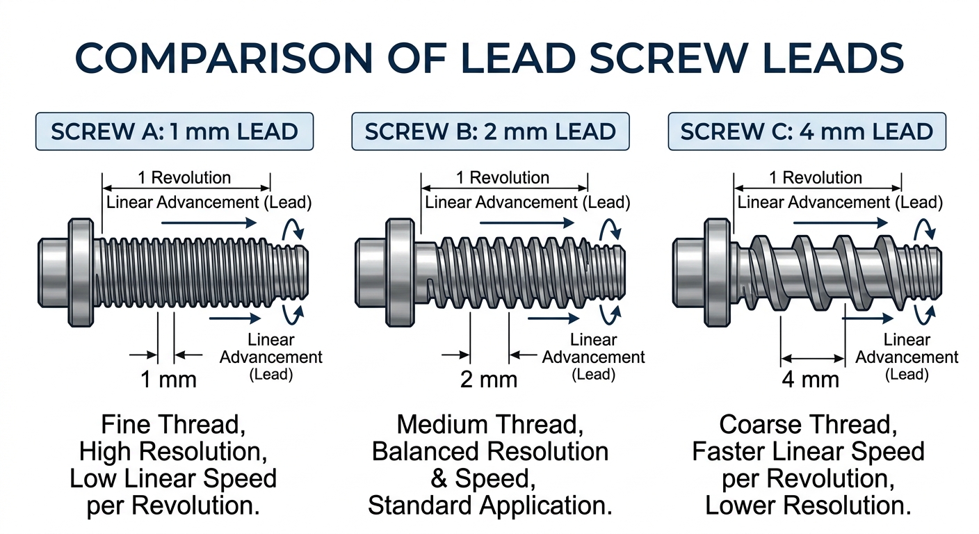
Step 2 — Pick the Lead, Then Compute Screw Torque
Lead is the lever you have the most control over. A finer lead (say 1 mm/rev) gives you mechanical advantage — less motor torque needed, but slower travel. A coarser lead (4 mm/rev) is faster but demands more torque.
Torque required at the screw shaft (before any gearbox) is:
Tscrew = (F × L) / (2π × ηscrew)
For our 35 N load on a 2 mm lead ACME screw at η = 0.4:
Tscrew = (35 × 0.002) / (2π × 0.4) = 0.0279 N·m ≈ 27.9 mN·m
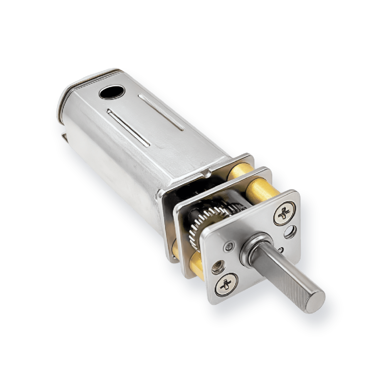
That's the torque the screw needs at its input. If you couple the motor directly to the screw (no gearbox), the motor has to deliver that 27.9 mN·m continuously. Most 12 mm coreless or brushed DC motors can't — which is exactly why we add a gearbox.
Worth noting: ball screws change the math significantly. With η ≈ 0.9, the same load only needs ~12.4 mN·m at the screw. But ball screws aren't self-locking, so a vertical actuator will back-drive when power is cut. Trade-off territory.
Step 3 — Derive the Gear Ratio from Speed
Gear ratio isn't a guess. It's fixed by two numbers you already know: your motor's rated no-load speed and your required linear velocity.
i = (nmotor × L) / (60 × v)
Where nmotor is in RPM, L in meters, and v in m/s.
Say you've chosen a 12 V brushed DC motor with 6,000 RPM no-load speed. You need the actuator to move 20 mm/s with a 2 mm lead screw:
i = (6000 × 0.002) / (60 × 0.020) = 10
So a 10:1 planetary gearbox. Easy. But here's the catch — motors don't run at no-load RPM under load. Plan for the motor to operate at roughly 70 – 80% of rated speed at your design torque. Re-run the math at 4,500 RPM and you'll see you actually need closer to 7.5:1, or you accept slightly slower motion.
For most compact actuator builds we see, ratios land between 5:1 and 100:1. Above that, you're either moving very slowly or using a worm gear for self-locking.
Step 4 — Apply Safety Factors and Check Duty Cycle
The textbook formula gives you the minimum motor torque. Real designs need margin.
- Safety factor of 1.5 – 2.0 on calculated torque. Friction increases with wear, lubricant viscosity changes with temperature, and motors lose torque as they heat up.
- Continuous vs. intermittent duty. A motor rated for 30 mN·m continuous can briefly hit 80 mN·m, but only for seconds. If your actuator cycles 4 times per minute under near-max load, treat it as continuous duty.
- Stall protection. End-of-travel impacts are where small actuators die. Either add limit switches or use an encoder motor with current monitoring so the controller can detect a stall in milliseconds.
Back to our example: 27.9 mN·m × 1.8 safety factor ÷ gear ratio 10 ÷ gearbox efficiency 0.75 = 6.7 mN·m required at the motor shaft. A standard 12 mm planetary gear motor easily handles this — with plenty of headroom for the next product revision.
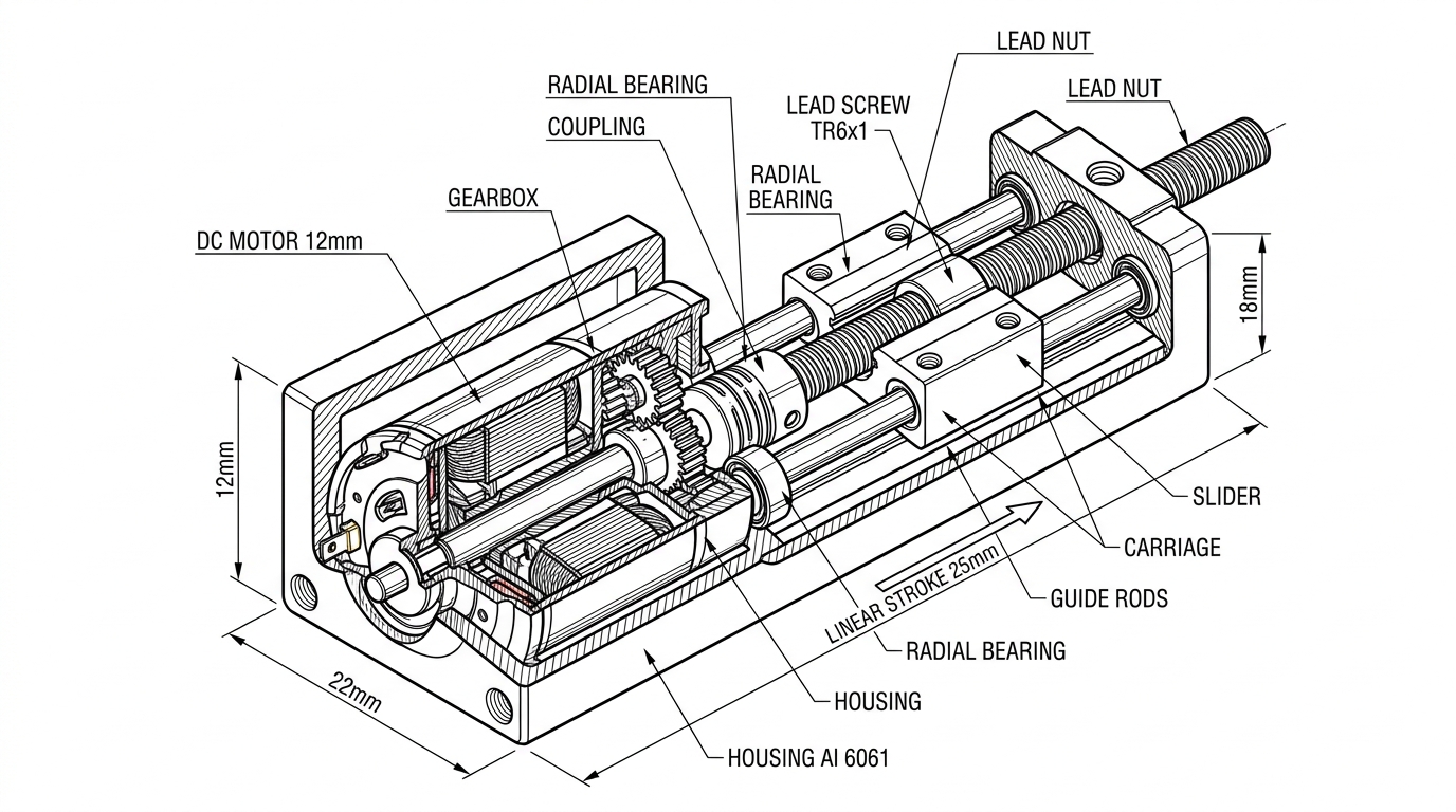
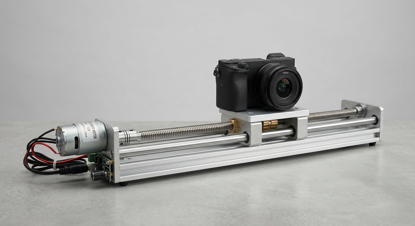
A Worked Example — Compact Camera Slider
Let's run the full sequence on a real project. An OEM building a tabletop camera slider asked us to spec the drive: 800 g camera payload, 60 mm/s travel speed, 200 mm stroke, horizontal motion on linear rails.
- Load force. Camera weight isn't lifted (horizontal), but rail friction ≈ 0.05 coefficient × 7.85 N weight = 0.4 N. Add 2 N for cable drag and acceleration. Design F = 5 N (with margin).
- Screw choice. 2 mm lead ACME screw, η = 0.4. Self-locking so the camera holds position when powered off.
- Screw torque. T = (5 × 0.002) / (2π × 0.4) = 4 mN·m.
- Gear ratio. Using a 16 mm brushed DC motor at 9,000 RPM no-load, target 60 mm/s: i = (9000 × 0.002) / (60 × 0.060) = 5. We picked 6:1 to keep the motor in its efficient zone.
- Motor torque needed. 4 mN·m × 1.8 safety ÷ (6 × 0.8 gearbox η) = 1.5 mN·m. A small coreless DC gear motor handles this with ~30% load — quiet, smooth, long life.
Total package: roughly 18 mm diameter, 55 mm long, drawing under 200 mA at speed. That's what good sizing looks like.
Matching Motor Type to the Calculation
Once you have the torque and speed numbers, motor selection is mostly a process of elimination.
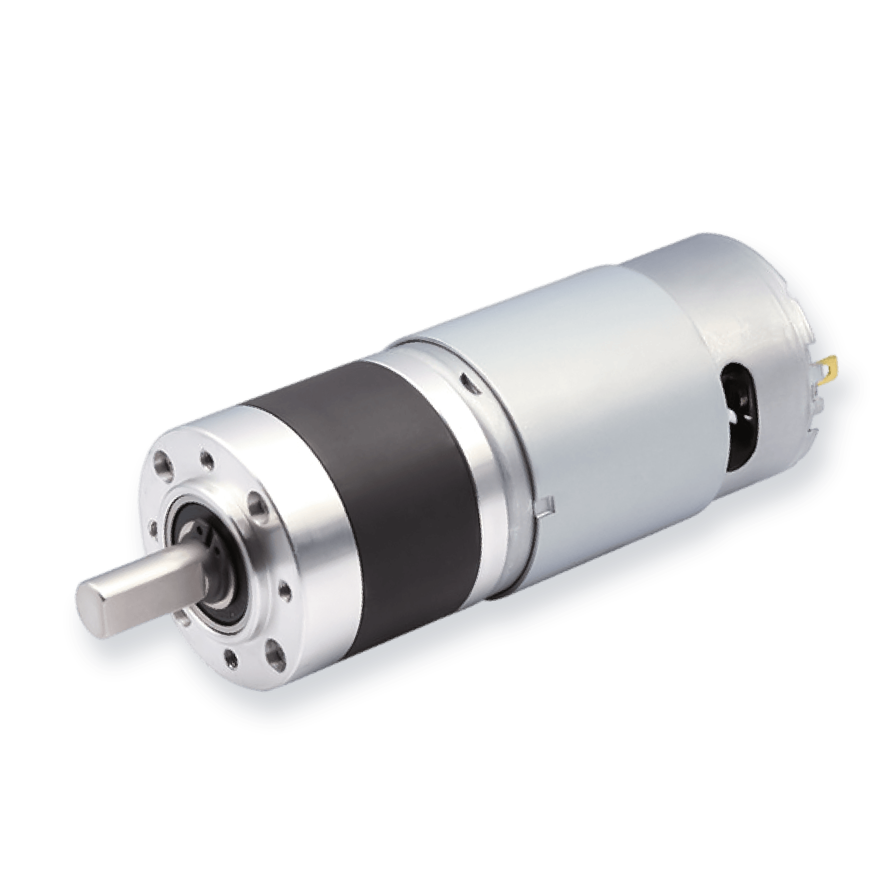
Brushed DC gear motor
The default for cost-sensitive actuators under 50 N. Pair with a planetary or spur gearbox. Lifespan in continuous duty is the weak point — expect 2,000 – 5,000 hours depending on brush quality.
Brushless DC (BLDC) gear motor
Pick this when duty cycle is high or product life needs to clear 10,000 hours. Higher upfront cost, but no brush wear, better efficiency, and easier closed-loop control.
Stepper gear motor
The right call when you need open-loop position control without an encoder — small valve actuators, lab automation, dosing pumps. Watch holding torque versus running torque: steppers lose torque fast above a few hundred RPM.
Coreless DC motor
For very small, smooth, low-inertia actuators — medical pumps, optical adjusters. Excellent acceleration and quiet operation, but limited continuous torque.
If none of the standard combinations match your envelope, this is where a custom gearbox earns its keep. Brief background on motor families is in our DC motor types guide.
Common Sizing Mistakes That Burn Out Actuators
Five errors we see repeatedly in customer designs:
- Using no-load motor speed in the gear ratio calculation. Motors slow down under load. Always derate to ~75% of rated speed for sizing.
- Ignoring screw efficiency. Datasheet says “ACME screw” — fine, but η can be anywhere from 0.25 to 0.50 depending on material, lubrication, and lead angle. Assume the lower end.
- Forgetting gearbox efficiency stacks. Each planetary stage costs ~10% efficiency. A 3-stage 100:1 gearbox is closer to 70% efficient, not 90%.
- Skipping the holding torque check. For vertical actuators with back-drivable screws, the motor or brake must hold position when unpowered. Self-locking ACME or worm-driven designs sidestep this.
- No thermal margin. A motor running at 95% of rated torque continuously will overheat. We covered this in detail in why micro gear motors overheat.
Putting It Into Your Next Design
The workflow boils down to four numbers in this order: load force, screw lead, gear ratio, motor torque. Calculate them in sequence, apply a 1.5 – 2× safety factor, then pick the smallest motor that still has thermal headroom for your duty cycle. Don't optimize for the lightest motor — optimize for the one that will still be working in year three.
If you'd like a second pair of eyes on your actuator sizing, or you need a compact gear motor matched to a specific torque-speed point, the SLW Motor engineering team can run the numbers with you and recommend a stock or custom configuration. Browse our compact motor and gearbox catalog or send us your specs — load, stroke, speed, voltage, and envelope are usually enough to get started.